In this post, another mini GPIO project will be presented by using only LEDs. I’ll make LEDs count in binary format up to 64 using 6 of them.
Main code will be put inside an infinite loop so that chip always goes on counting.

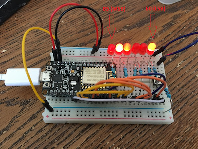
Figure: Rightmost LED represents Least Significant Bit (LSB) whereas leftmost LED represents Most Significant Bit (MSB) as depicted in the figure
Setting Up Circuitry
- GPIO 16, GPIO 5, GPIO 4, GPIO 0, GPIO 2, GPIO 14 pins will be configured as Output pins being pin_D0, pin_D1, pin_D2, pin_D3, pin_D4, pin_D5 respectively.
CODE
Coding will be too easy for this project but only tricky part would be the function that gets a decimal number and converts that number into binary format.
def DisplayBinary(decimalNumber):
# format given decimal…convert to binary..Total number of bits is 6…zero padding….
binaryString = ‘{0:06b}’.format(decimalNumber)
pin_D0.value(int(binaryString[5]))
pin_D1.value(int(binaryString[4]))
pin_D2.value(int(binaryString[3]))
pin_D3.value(int(binaryString[2]))
pin_D4.value(int(binaryString[1]))
pin_D5.value(int(binaryString[0]))
For complete code, see here => https://github.com/mdemiray/MicroPython-BinaryCounterLED
Summary
Another GPIO project using LEDs as output GPIO is presented in this post.
Have fun!
Test Environment
Chip Used: ESP8266 NodeMCU (Flash Size 4 MB)
Firmware Used: esp8266-20171101-v1.9.3.bin
Circuit Components: 1K Resistors, LEDs, Jumper Wires


![[Tiny-Tech-Tip] Locking Mac computers quick: Command + L](https://remidemiray.com/wp-content/uploads/2025/02/before-after-command-lock.png?w=545)


![[Master Thesis] A Novel Method For the Quantification of Coronary Artery Stenosis: A 2D QCA SYSTEM](https://remidemiray.com/wp-content/uploads/2025/01/gui.jpg?w=548)

Leave a comment